Half-duplex UART (RS485) on ESP32
Posted on Sun 26 April 2020 in microcontroller
I'm a happy owner of a few ESP32 microcontrollers. These are similar to the Arduino, but have WiFi & Bluetooth built in, which makes them very versatile. These chips come with a lot of peripherals, including three UARTs. These allow offloading the actual bit-banging of the pins to dedicated hardware, freeing up the main processor for more useful work.
Normally, UARTs work in full-duplex mode: they can send and receive simultaneously over separate wires. (Obviously, you can operate it in simplex mode as well, by only sending or receiving.) Half-duplex means that the device can both send and receive, but not simultaneously. This post is about getting this half-duplex mode to work, which was more tricky than it should have been.
Half-duplex is used by RS-485, but also open-drain (or open-collector in bipolar terminology) buses are inherently half-duplex. The ESP's documentation refers to its half-duplex provisions by the RS-485 name.
Challenges
Half-duplex works just like full duplex when only one device is transmitting at a time. So for simple request-response protocols with only a single pair of endpoints, this usuall doesn't matter. It becomes more challenging when multiple devices may initiate a conversation:
Before starting a transmission, the device should first check if the bus is free. I.e. if there is no-one else transmitting at that time. If the bus is busy, the device should hold off its transmission until it is free.
Even during a transmission, the device should monitor the bus to see if it can see its own transmission correctly. Ideally, it should be able to detect a "collision", and retransmit in that case.
Test setup
To perform the test, I tested a single ESP32 against itself: UART2 is the device under test, UART1 is used as a reference, and kept in full-duplex mode. The half-duplex magic is done by abusing the second core the ESP32 offers: I looped back the Tx and Rx pins to GPIO pins and logically ANDed them:
gpio_set_direction(GPIO_NUM_27, GPIO_MODE_INPUT);  // connected to UART1 Tx
gpio_set_direction(GPIO_NUM_26, GPIO_MODE_INPUT);  // connected to UART2 Tx
gpio_set_direction(GPIO_NUM_25, GPIO_MODE_OUTPUT);  // connected to UART1 & UART2 Rx
for(;;) {
    int level1 = gpio_get_level(GPIO_NUM_27);
    int level2 = gpio_get_level(GPIO_NUM_26);
    // idle level is 1
    // if either Tx asserts 0, output 0
    int level = level1 & level2;
    gpio_set_level(GPIO_NUM_25, level);
}
The test consists of 4 parts (source code):
- Receive only
- Transmit only
- Transmit while bus is busy
- Transmit with collision
The first two parts are trivial, but are included for completeness. The third test should reveal if the device waits for the bus to become available before starting a transmission. The forth test will always result in corruption, but the sender should report this.
Full duplex mode
As a reference test, I set up UART2 similar to UART1:
uart_config_t uart_config = {
    .baud_rate = 9600,
    .data_bits = UART_DATA_8_BITS,
    .parity    = UART_PARITY_DISABLE,
    .stop_bits = UART_STOP_BITS_1,
    .flow_ctrl = UART_HW_FLOWCTRL_DISABLE,
};
ESP_ERROR_CHECK(uart_param_config(UART_NUM_2, &uart_config));
ESP_ERROR_CHECK(uart_set_pin(UART_NUM_2, GPIO_NUM_16, GPIO_NUM_17, UART_PIN_NO_CHANGE, UART_PIN_NO_CHANGE));
ESP_ERROR_CHECK(uart_driver_install(UART_NUM_2, 1024, 1024, 0, NULL, 0));
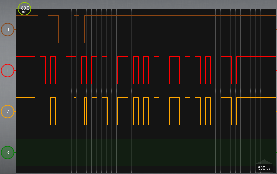
As expected, part 1 & 2 returned the expected data; During test 3, UART2 failed to wait until the bus was free (as expected), which garbled the resulting output: (0) is UART1's output (reference), (1) is UART2's Tx (DUT), (2) is the resulting Rx signal given to both UARTs.
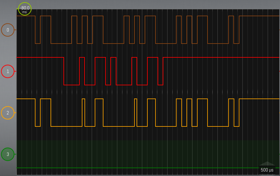
Instead of receiving the "CCCC" (sent by UART1) or the "dd" (sent by UART2), garbage was received:
03 80 a8 e8 |....|
Test 4 failed in the expected way as well. UART2 was transmitting "eeee", while UART1 sent "F" simultaniously, colliding in the first byte.
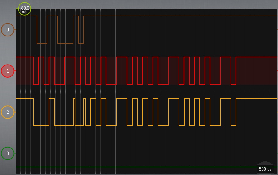
04 65 65 65 |.eee|
RS485 modes
The ESP's documentation is very sparse on its half-duplex capabilities. The technical reference manual mentions the "RS485 mode configuration" register, but no further explanation is given. The ESP-IDF programming guide goes in to a bit more detail, describing the different modes to connect to a 485 bus. Its API provides three modes that look interesting: UART_MODE_RS485_HALF_DUPLEX, UART_MODE_RS485_COLLISION_DETECT and UART_MODE_RS485_APP_CTRL.
UART_MODE_RS485_HALF_DUPLEX
In RS485_HALF_DUPLEX mode, contrary to my expectations, nothing happened: test 1 & 2 still passed, test 3 & 4 still failed in a very similar way.
Test 3 failed to wait for the bus to free up, and returned garbage data:
03 80 a8 e8 |....|
Test 4 got corrupted as well.

04 65 65 65 |.eee|
In this mode, you can use the uart_get_collision_flag() function to see if there was a collision. It returned false for test 1 (as expected), but true for tests 2, 3 and 4 (only 4 was expected).
UART_MODE_RS485_COLLISION_DETECT
This setting paniced. I haven't figured out why (yet).
UART_MODE_RS485_APP_CTRL
RS485_APP_CTRL mode was indistinguishable from HALF_DUPLEX in my tests:
Test 3 failed to wait for the bus to free up, and returned garbage data:
03 80 a8 e8 |....|
Test 4 got corrupted as well.
04 65 65 65 |.eee|
uart_get_collision_flag() returned false, true, true, true.
Custom RS485 modes
From the tests above, it is clear that neither of the provided modes perform the desired functionality. Time to dig in deeper.
The ESP-IDF SDK is nothing more than a set of provided library functions that abstract away the register manipulations. uart_set_mode() for example manipulates the UART_RS485_CONF_REG register (accessed as UART[uart_num]->rs485_conf in ESP-IDF). The code shows that all three modes activate RS485 mode (UART[uart_num]->rs485_conf.en = 1), but they differ in the settings of the other flags.
What surprised me, is that all three modes set
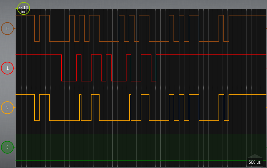
UART_RS485RXBY_TX_EN/rx_busy_tx_en flag: enable the RS-485 transmitter to send data, when the RS-485 receiver line is busy. As soon as that was turned off, things started looking better: UART2 waited for the bus to free up before transmitting its "dd" message, which resulted in the correct sequence being received. The collision flag was still wrong (it indicated collisions in test 2 & 3 as well).
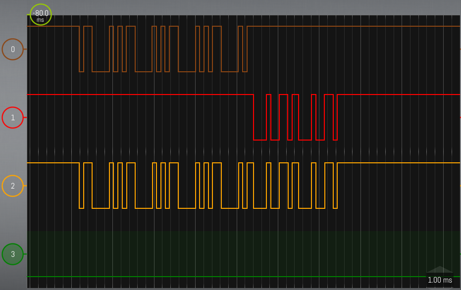
43 43 43 43 64 64 |CCCCdd|
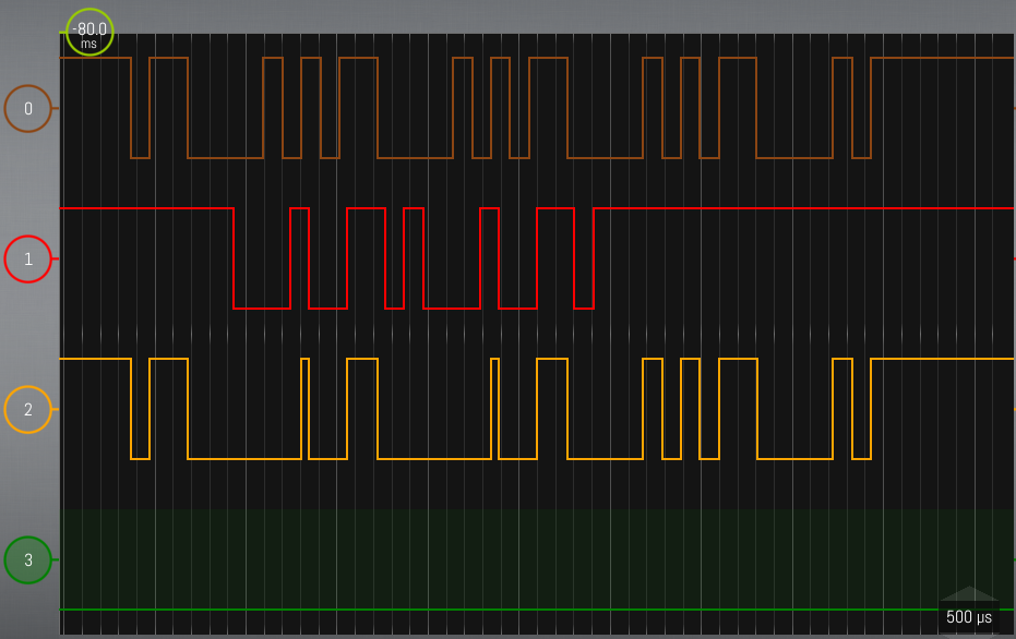
Another flag that is available is the UART_RS485TX_RX_EN/tx_rx_en, which will enable the transmitter’s output signal loop back to the receiver’s input signal. The APP_CTRL mode (which I used as a starting point) leaves this flag off. I expected this to suppress receiving my own transmissions, but instead, it returned a 0x00-byte for every byte transmitted. So let's try setting this to 1.
This seems to be the magic combination: Tx waits until the bus is free, and the collision flag yields the expected result (only true for test 4). It only introduces a small problem:
E (1398) uart: uart_get_collision_flag(1568): wrong mode
The uart_get_collision_flag() reads out the collision state as reported by the SDK. And the SDK doesn't track the collisions when in APP_CTRL. But nothing is stopping us to do that ourselves: The hardware sets the UART_RS485_CLASH_INT_RAW bit in the UART_INT_RAW_REG register. This can trigger an actual interrupt if enabled, but we are only interested in finding out if a clash happened, not exactly when it happened. So we can simply read out this register, and clear it before the next transmission:
UART2.int_clr.rs485_clash = 1;  // clear bit
uart_write_bytes(UART_NUM_2, "whatever", 8);
bool collision_happened = UART2.int_raw.rs485_clash;
Conclusion
For my purpose, I wanted the transmision to be kept back if the bus is busy. I also wanted to have accurate collision reporting. The following code sets this up for me:
uart_config_t uart_config = {
    .baud_rate = 9600,
    .data_bits = UART_DATA_8_BITS,
    .parity    = UART_PARITY_DISABLE,
    .stop_bits = UART_STOP_BITS_1,
    .flow_ctrl = UART_HW_FLOWCTRL_DISABLE,
};
ESP_ERROR_CHECK(uart_param_config(UART_NUM_2, &uart_config));
ESP_ERROR_CHECK(uart_set_pin(UART_NUM_2, GPIO_NUM_16, GPIO_NUM_17, UART_PIN_NO_CHANGE, UART_PIN_NO_CHANGE));
ESP_ERROR_CHECK(uart_driver_install(UART_NUM_2, 1024, 1024, 0, NULL, 0));

uart_set_mode(UART_NUM_2, UART_MODE_RS485_APP_CTRL);
UART2.rs485_conf.rx_busy_tx_en = 0;  // don't send while receiving => collision avoidance
UART2.rs485_conf.tx_rx_en = 1;  // loopback (1), so collision detection works

bool did_collision_happen_since_last_check() {
    bool ret = UART2.int_raw.rs485_clash;
    UART2.int_clr.rs485_clash = 1;  // clear bit
    return ret;
}