Controlling SMA inverters via ModBus
Posted on Thu 07 May 2026 in energy
Harnessing the power of solar energy has become an important step toward a sustainable and energy-efficient home. An key component are solar inverters and home battery systems, which work together to convert sunlight into usable electricity and store excess energy for later use. Controlling these systems effectively can maximize energy savings, but can also optimize the cost/profit when combined with a dynamic energy contract.
Most vendors provide some form of energy management system with their home batteries. It typically uses solar surplus power to charge the battery, and uses battery power to cover periods with solar deficit. But what if you want to something more fancy?
I have a system from SMA. Their Energy Management System (EMS) is called the Home Manager, and it works fairly well, but also has some downsides:
- [+] It does basic PV surplus to battery and PV deficit from battery
- [+] It supports "peak shaving" to optimize around the "capacity tariff"
(a tariff in Flanders that is related to your peak power demand as opposed to energy consumption). - [-] Management of your settings is only possible through the SMA cloud via the internet,
and it takes about a minute for changes to be applied. - [-] The peak shaving algorithm is suboptimal. The peaks are calculated as total energy per 15 minutes.
This means that you can go over your peak during the last 5 minutes if you were under in the first 10 minutes.
The HM does not use this opportunity.
Luckily, you can also ditch the Home Manager, and control the inverters yourself via Modbus. Here is what I found out about that.
Sunny Boy
My first inverter is a Sunny Boy. SMA publishes the Modbus registers in the Downloads section, so that made things a lot easier. One thing to note is that most writeable parameters have a "Warning against cyclical writing". Since these parameters are committed to Flash every time you change them, doeing so often will wear out the storage of the inverter.
There are four registers that seem interesting, none of them are marked as “avoid cyclical writing”:
- 40016, Normalized active power limitation by PV system control,
Inverter.WModCfg.WCtlComCfg.WNom - 40023, Normalized active power limitation by PV system control,
Inverter.WModCfg.WCtlComCfg.WNomPrc - 40149, Active power setpoint,
Inverter.WModCfg.WCtlComCfg.WSpt - 44425, Active power setpoint,
Inverter.WModCfg.WCtlComCfg.WSpt
On my machine, both "Active power setpoint" registers didn't seem to do anything. Writing to 40023 however does work. Here is a Python snippet to curtail to 1% production:
from pyModbusTCP.client import ModbusClient

host = "192.0.2.1"
unit_id = 3

def reg_encode(value: int | float, size: int = 16, fix: int = 0, signed: bool = True) -> list[int]:
   """
   Encode a value into a list of integers to write to sequential registers.
   """
    v = int(value * (10**fix))
    b = v.to_bytes(length=size//8, byteorder='big', signed=signed)
    words = [int.from_bytes(b[i:i+2], byteorder='big', signed=False) for i in range(0, len(b), 2)]
    return words

def reg_decode(regs: list[int], fix: int = 0, signed: bool = True) -> int | float:
   """
   Decode a series of registers into the corresponding value.
   """
    b = b''.join([reg.to_bytes(length=2, byteorder='big', signed=False) for reg in regs])
    v = int.from_bytes(b, byteorder='big', signed=signed)
    value = v / (10**fix)
    return value

c = ModbusClient(host=host, port=502, unit_id=unit_id, auto_open=True)

grid_out = reg_decode(c.read_holding_registers(30775, 2))
print("Current AC power: {grid_out}")

curtail_percent = 1.0
c.write_multiple_registers(40023, reg_encode(curtail_percent, size=16, fix=2, signed=False))
Note that the response isn't immediate. This means care should be taken to avoid oscillating.
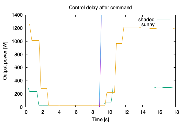
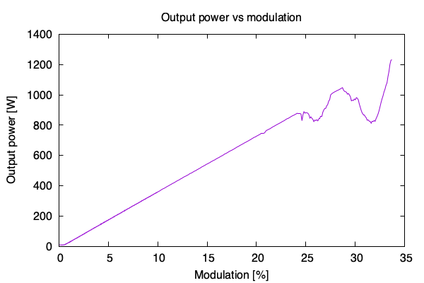
But if you give the inverter a couple of seconds to stabilize (3 seconds for the graph below), the control is surprisingly linear. The dips starting at 25% are clouds ruining my test.
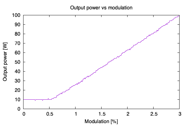
And it doesn't seem to be possible to modulate entirely down to 0%:
Sunny Boy Smart Energy
The second machine is a hybrid invertor, the Sunny Boy Smart Energy (SBSE). Besides solar panels, it also has a battery attached for energy storage. This means that I want to have control over battery charging and discharging, as well as PV curtailment. Here also, you can find the Modbus registers in the downloads section.
It took a bit of experimenting, but the following registers seem to work for curtailing and battery management:
- 41431 and 41433: Maximum/Minimum active power,
Setpoint.PlantControl.Inverter.WModCfg.WCtlComCfg.WSptMaxand...WSptMin - 41467 and 41469: Max/Min setpoint value for active power of storage,
Setpoint.PlantControl.Bat.WCtlCom.WSptMaxand...WSptMin
Both are marked as "Device Control Object", so it should be safe to write to those often. The second pair of registers (41467 and 41469) seem to control the generation power of the battery. So positive values mean discharging, negative values mean changing. When being controlled by the Home Manager, I can see that the WSptMin stays at -15000 W, while the WSptMax is constantly modified to match the current situation. When it's sunny it goes down to -1000 W (charging the battery), when a cloud takes the sunlight away, it goes up to +500 W (discharging the battery).
The following Python snipped will set your battery to charge at 500 W. Note to disconnect your Home Manager, since it will overwrite this setting immediately. Also note that the inverter may have a timeout and fallback configured, so it may stop doing what you sent after some time.
# ... Same boilerplate as above ...

bat_ch = reg_decode(c.read_holding_registers(31393, 2), signed=False, fix=0)
bat_dis = reg_decode(c.read_holding_registers(31395, 2), signed=False, fix=0)
bat_max = reg_decode(c.read_holding_registers(41467, 2), signed=True, fix=0)
bat_min = reg_decode(c.read_holding_registers(41469, 2), signed=True, fix=0)
print(f"Battery power: {bat_ch} W ch, {bat_dis} W disch = {bat_dis - bat_ch} W from battery; setpoint [{bat_min}, {bat_max}]")

storage_power = [-15000, -500]
c.write_multiple_registers(41467, [
   *reg_encode(storage_power[1], signed=True, fix=0, size=32),
   *reg_encode(storage_power[0], signed=True, fix=0, size=32),
])
The other pair of registers (41431 and 41433) control the output of the whole inverter towards the grid. Here also, positive values mean energy is being pushed towards the grid, negative values means the inverter is consuming power. Typically, the Home Manager leaves these at -5000 W and 5000 W for my 5kW unit, although I've seen it put the WSptMax lower.
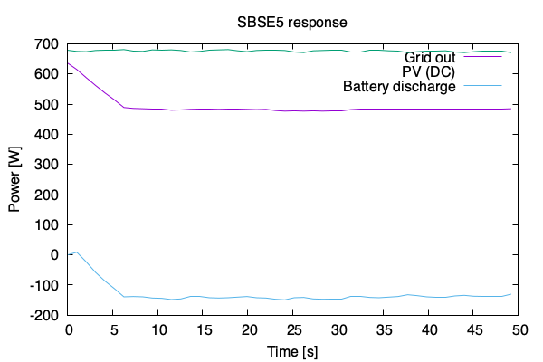
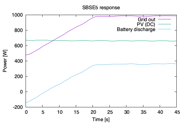
Since the settings are ranges, the inverter typically does "the right thing". For example, with 700W of solar, and a set maximum of 500W grid export, the inverter will put excess PV into the battery. Note that these control changes happen slowly, over about 5 seconds.
Requesting the battery to discharge at 1.5kW, while limiting the grid output to 1kW causes the inverter to reduce the battery discharge and keep within the 1kW grid limit. This is expected, since the output from the battery is still within the configured limits of -15kW and +1.5kW. Here the control slope is limited to about 23W/s.
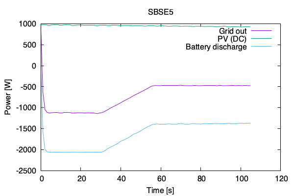
We can also give conflicting instructions. Say you command "discharge the battery between -15kW and -2kW" (i.e. charge at 2kW), and you limit "grid output between -500W and +5kW" (i.e. max 500W consumption). If there is not enough solar power, the inverter will initially follow the battery constraint, but after about 30 seconds gently fall back to get within the grid constraints.
Let's say you are on a Dynamic Tariff and there are highly negative prices around midday. You may want to discharge the battery now (while you are still getting paid for putting energy on the grid), so that you can recharge it later from grid power when the prices are negative (and thus you are getting paid to consume energy). To drain your battery now, you want to command "discharge between +5kW and +5kW". But there is no direct control over PV power, so the actual discharge rate is limited by the 5kW grid output minus the PV production. So if you really want to discharge your battery, you need to walk up to the inverter and disconnect the PV arrays.
Around midday that same hypothetical day, you want to configure for maximum grid usage. Also here, since there is no direct control over PV generation, you are limited. But since the battery can charge up to 10kW, the limit will be the energy storage capacity of the battery, and not the grid power: I tested "discharge between -15kW and -6kW" (i.e. charge) along with "grid export between -5kW and -4.5kW" (i.e. import). This resulted in a 6kW charge, but only a 2.5kW grid import (+3.5kW from solar). So the inverter ignored the grid control, but this still allows you to pull in maximum 5kW from the grid as long as your battery has place to put the energy.